Lighting and Illumination Systems [Demo]
Nowadays, lighting systems are mostly equipped with electronic ballasts (ECGs) and, with increasing tendency, with LED technology. However, in addition to the advantages these offer, their disadvantages must also be taken into account:
- Mostly capacitive loads, thus risk of grid resonances
- Very sensitive to commutation dips, switching operations or superimposed high frequency on the line voltage
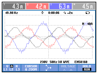
In the picture below a typical feedback oscillation can be seen in L2 and L3, recognizable by the ondulation (=high-frequency superposition) in the top area. This ondulation should not be existing, please compare with phase L1.

Picture 0019: Ondulation in the top area
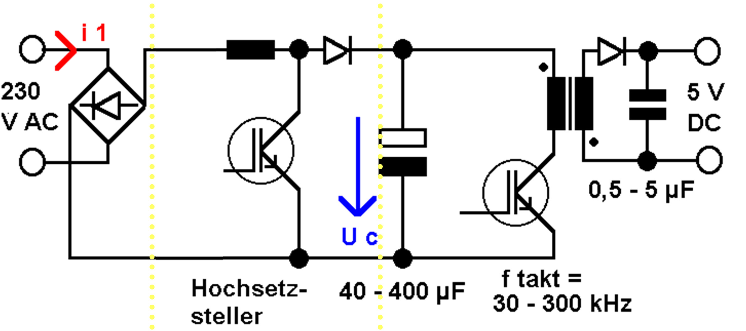
The following picture shows the boost converter circuit for the power factor correction between the yellow dots. The controller works in such a way that the current is already "pumped up" against the DC-link voltage from the beginning of the sine wave. Thus, there is no need to wait until the peak of the voltage, a sinusoidal current consumption can therefore be achieved.

Scheme 0002: Switching power supply unit with power factor correction circuit (PFC)
The boost converter requires its own control loop, which is an oscillating structure.
Converter power supply units operate on the basis of pulsed direct current. This requires a controller which, depending on the design, can be sensitive to resonances. As shown, controllers are almost always oscillatory, and excitations with such high frequencies sometimes disturb controllers. As a result, the destruction of the DC-link smoothing capacitor often occurs.
See Harmonics and Grid Resonances for more information on this topic.


