Harmonics - Understanding and Interpreting Measurement Pictures (Waveform, etc) [Demo].
Harmonics are mainly generated by rectifiers.
powerqualityonline shows you the typical measurement pictures (waveform, etc) and what they mean, assisting you in understanding and interpreting.
In addition, we explain how to proceed with the measurement.
Single-Phase Rectifiers
The following picture shows a single-phase rectifier as an example. For measurement, please also refer to practice harmonics.
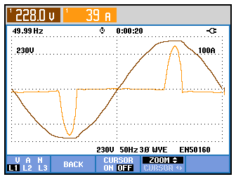

Figure 0271: Typical current and voltage waveform recorded by a single-phase rectifier
Flattened Voltage Curve (Sign Waveform)
It is clearly visible above that the voltage curve is flattened by the current.The current curve is shown in the picture below (spectrum). Each bar represents a frequency. In this example, the cursor is on the 3rd harmonic, i.e. 3 x 50 Hz = 150 Hz. Its share is thus 53.7 % in relation to the fundamental.
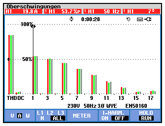
Fig. 0275: Spectrum of the current of the single-phase rectifier
Narrow Current Pulse
The next example shows a narrower current pulse of a single-phase rectifier. The reason is a larger DC-link capacitor (smoothing electrolytic capacitor) than in the example above.The effect is that more harmonics are generated and the spectrum extends further up to higher frequencies. In terms of EMC, the interference potential is higher.
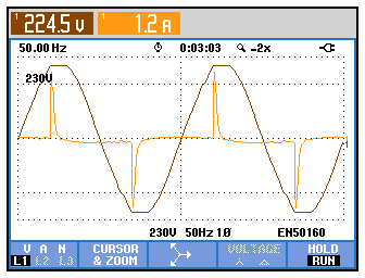
Figure 0001: Typical current waveform absorbed by a single-phase rectifier
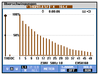
Figure 0002: Associated spectrum
In this case, the pulses are very narrow, the harmonics go far into the upper frequency range in the spectrum. If the pulses are wider or more "rounded" in shape, the spectrum of the harmonics falls faster (see fig. 0271 above). In this example the total distortion is selected with the cursor => THD is 203 % in the example, i.e. the current contains twice as much harmonic content as the fundamental.Double Current Peaks with Three-Phase Current
There is a similar picture for three-phase current (rectification by means of a B6 bridge), but with double current "peaks" and a different distribution in the spectrum:
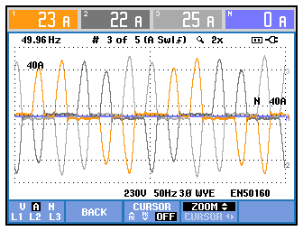
Fig. 0003: Typical curve of the current at the input of a three-phase bridge rectifier with capacitor (without choke coil) in the DC link (DC-bus)
The current shows the following spectrum: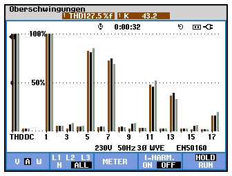
Figure 0004: Associated spectrum, clearly visible are the 5th/7th harmonic, the 11th/13th harmonic, the
17th/19th harmonic, etc.
Harmonics divisible by 3 (3rd/6th/9th/12th etc.) are not existing.17th/19th harmonic, etc.
Active Rectifiers
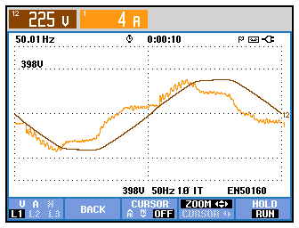
Figure 0005: Example of current draw of a single-phase power supply unit with active rectifier
UL1 brown, IL1 light brown
By means of boost converters in the input of the power supply units, the supply current is not only picked up in the range of the peak value, but also in ranges below the peak value within the 20 ms period. Current can thus also be "pumped up" into the DC link (DC-bus) in the sections of low voltage in the sinusoidal waveform. An attempt is made to achieve a current draw that is as sinusoidal as possible. Theoretically, a harmonic-free load with cos phi = 1 can be achieved this way (i.e. = resistive load). In practice, this is usually not quite successful, as high frequency is also generated by the pulsation caused by the boost converter in the input of the power supply units.UL1 brown, IL1 light brown
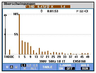
Fig. 0006: Associated spectrum
Active rectifiers are also used for three-phase current. If you see such a voltage superimposed with high frequency in your measurement, it is recommended to search for corresponding rectifier systems in your grid: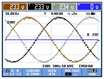
Figure 0007: Strong superposition of high frequency on the line voltage
High-Frequency Superposition
This superposition is caused by active rectifiers, which are supposed to draw a sinusoidal current from the grid by pulsing which is typical for many multi-axis drives and also 4-quadrant controllers. On closer inspection, double zero crossings can be seen in L2 (black). They are a cause of many control-related problems.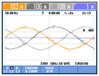
Fig. 0007a: Current draw of an active rectifier
This current draw is the cause of the high-frequency superposition of the voltage.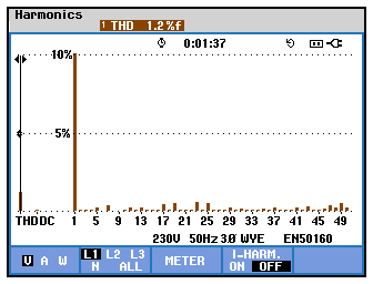
Fig. 0008: Spectrum of the voltage
The "classical" low-frequency harmonics (3rd/5th/7th, etc.) have almost disappeared.High-frequency superposition often exceeds the 50th harmonic (i.e. > 2500 Hz) and is no longer visible in the spectrum (with usual power quality analyzers).
The standard EN 50160 only considers up to the 40th harmonic (= 2kHz) anyway. Thus, high-frequency superposition is often not detected by classical power system analysis.
We recommend the use of wideband measurement equipment, specifically:
Insulated, portable oscilloscopes.
Attention:
For safety reasons, do not use grounded oscilloscopes or oscilloscopes equipped with a metal housing. For this type of measurement, it is essential to use ungrounded and insulated equipment with a specification of at least CAT III 1000 V / CAT IV 600 V, e.g. Fluke ScopeMeter Series 120, 225 or 190 II.
To disconnect the protection earthing (PE) of oscilloscopes from ground/earth
(possibly even those with metal housings or other touchable parts) is life-threatening and therefore forbidden.
Work safety is not observed with such a procedure!
Please note the zoom of the spectrum to a scale of 10 % to the upper edge of the picture in this case.
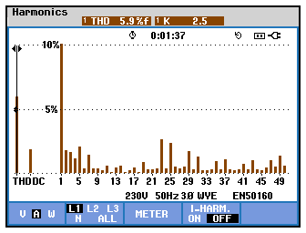
Fig. 0008a: Spectrum of the current
Even-numbered components in the lower frequency range (which normally do not occur in the grid) can be recognized - they are a consequence of the modulation of the active rectification, as well as "suddenly" appearing components starting from the 23rd harmonic and again far above around the 49th harmonic. These irregularities are typical for active rectifiers.Please note the zoom of the spectrum to a scale of 10% to the top of the image in this case.
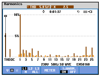
Fig. 0008b: Spectrum of the current of an active rectifier
Interharmonics
Active rectifiers (also called converters with active front end) generate interharmonics too , i.e. frequencies which are not divisible by 50 Hz (examples: 725 Hz, 873 Hz, etc.).While the dark brown bars represent the "normal" (i.e. divisible by 50 Hz) harmonics, the light brown bars represent the interharmonics. Only one phase is shown, L2 and L3 usually look the same. The colors are for L1. It would be dark gray/gray for L2 , and for L3 it would be light gray/very light gray.
Please note the zoom of the spectrum to a scale of 10% to the top of the image in this case.
Please note the zoom of the spectrum to a scale of 10% to the top of the image in this case.
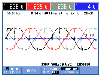
Fig. 0009: Voltages UL1, UL2, UL3, here in a color system with black/red/gray
The voltages show short dips which are caused by a power converter with thyristors, they are commutation dips.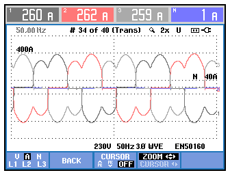
Fig. 0010: Oscillogram of the currents to the previous picture
The typical steep current transitions between the phases are visible, always when the next thyristor ignites.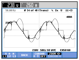
Fig. 0010a: Current and voltage in L1
If you look at a single phase, you can see that always at the point where the thyristor ignites, the current on this phase takes over and as a result of the short-time conduction of the commutating thyristor and the (still conducting) decommutating thyristor, a short-time voltage dip - the commutation dip - occurs.Dimmer
Dimmers generate harmonic spectra very similar to single-phase rectifiers (i.e. 3rd harmonic, 5th harmonic, 7th harmonic, etc.). The harmonic content depends on the phase angle or phase cut angle.
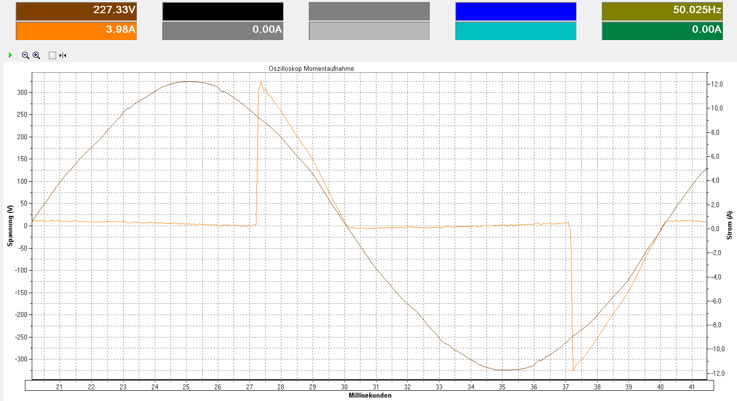
Fig. 0011: Phase angle by dimmer

Fig. 0012a: Spectrum of current at phase angle by dimmer
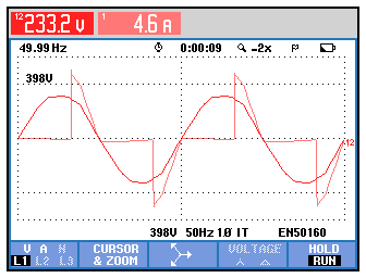
Fig. 0011a: Phase angle by dimmer, measured with Fluke 435
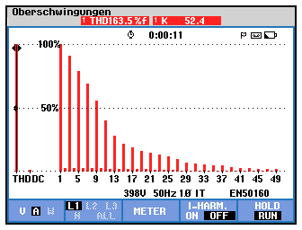
Fig. 0012: Spectrum of the current at phase angle by dimmer
The spectrum is very similar to the spectra of single-phase rectifiers; because of the steep turn-on edge, the current harmonics extend far up the frequency range.LED Lighting
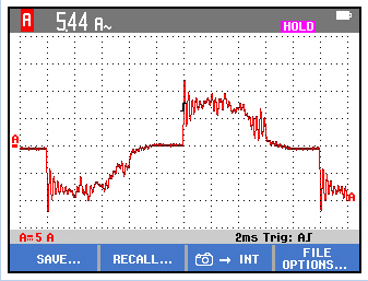
Fig. 0013: Oscillogram of LED lighting
A wide variety of power supply variants are used for LED lighting. In some cases, no switching converters or transformers are used, but only capacitors connected in series to the line voltage. These act as current limiters and result in the cheapest form of a power-supply unit for the LEDs.However, since capacitors "suck in" high frequency, there is a particular danger of grid resonance here and also of destruction of the LED lighting units.
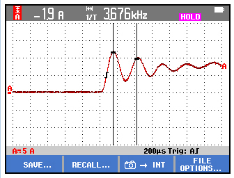
Fig. 0014: Measurement of high frequency in the overshoots from the example above
In this example, the overshoots resonate at a frequency of 3.676 kHz. This means that a classical power quality analyzer usually cannot measure this (it usually ends at 2.5 kHz = 50th harmonic).This can only be detected with wideband measurement equipment, such as oscilloscopes.
Attention:
For safety reasons, do not use grounded oscilloscopes or oscilloscopes equipped with a metal housing. For this type of measurement, it is essential to use ungrounded and insulated equipment with a specification of at least CAT III 1000 V / CAT IV 600 V, e.g. Fluke ScopeMeter Series 120, 225 or 190 II.
To disconnect the protection earthing (PE) of oscilloscopes from ground/earth (possibly even those with metal housings or other touchable parts) is life-threatening and therefore forbidden.
Work safety is not observed with such a procedure!


